Fluid mechanics design and optimization of an integrated fuel tank with dispenser
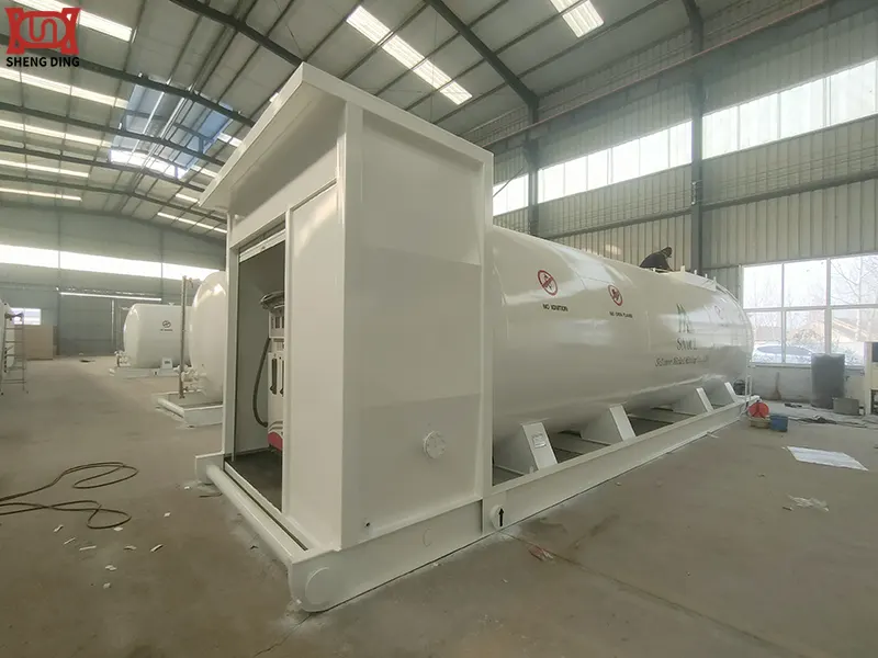
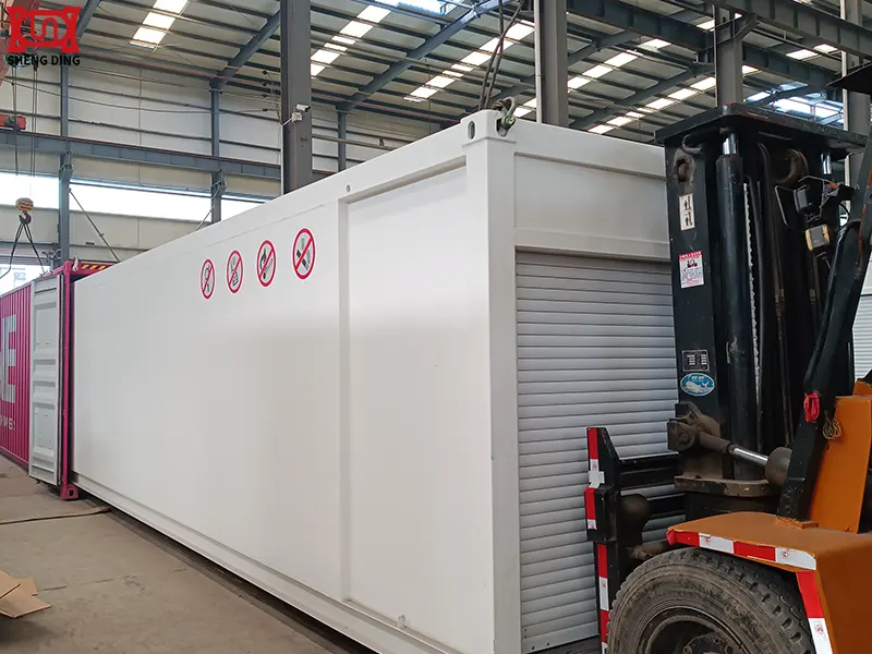
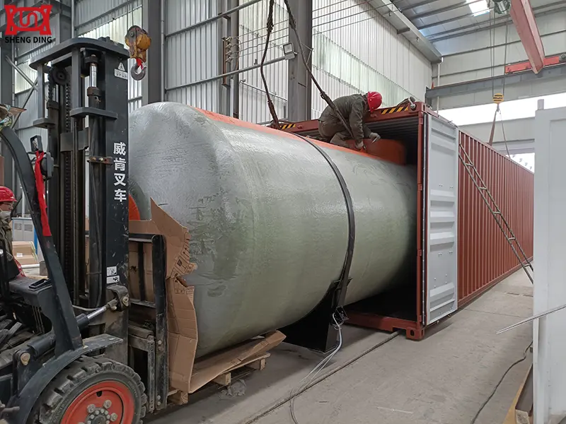
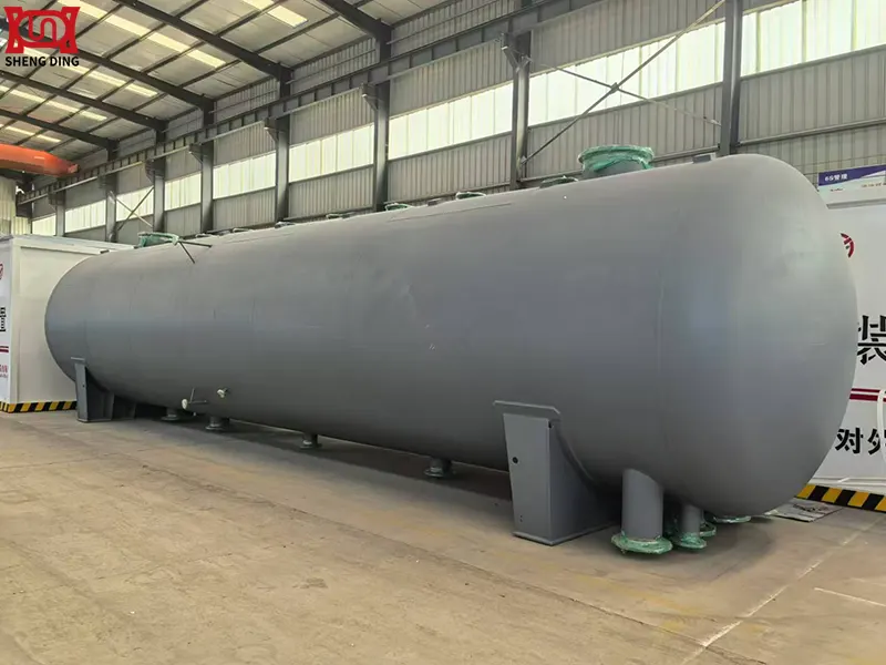
Integrated fuel tank with dispenser are currently a popular storage system for corporate fuel use. Their main advantages are flexibility, convenience, and safe storage, effectively solving internal fuel usage issues. Today, we will focus on the internal structural design of fuel tank with dispenser, focusing on how to minimize significant fluctuations in the oil content within the tank during operation.
I. Design Challenges and Goals
The integrated design combines the fuel tank and dispenser (typically an ejector or centrifugal pump) into one, saving space, reducing weight, and simplifying piping. However, this also presents unique challenges:
- Space Constraints: The pump, ejector, oil filter, valves, and other components must all be integrated, resulting in a compact layout and complex flow paths.
- Two-Phase Flow Issues: During refueling, violent sloshing of the oil surface and potential vortexes (vortex belts) at the refueling port can cause air to be drawn into the pump. During aircraft maneuvers, the fuel can also slosh violently, creating an oil-air mixture. These issues can lead to cavitation in the pump, reducing efficiency and even damaging it.
- Pressure Fluctuations and Hydraulic Shock: Pump startups and shutdowns, and valve openings and closings, can cause pressure fluctuations within the closed tank flow path, potentially impacting the structure.
- Full-Operating-Condition Adaptability: The system must operate stably under a wide range of operating conditions: from full to nearly empty; from horizontal to various tilted, accelerated, and vibrating positions; and from ground-based to aerial refueling.
- Thermal Management: The operation of the pump and the external environment heat the fuel, potentially generating fuel vapor and increasing the risk of cavitation.
- Maintainability and Reliability: The integrated design places higher demands on the reliability and maintainability of internal components.
Overall Design Objective: Achieve efficient, stable, and safe fuel delivery within a limited space, ensuring that the refueling pump effectively suppresses cavitation and maximizes fuel delivery (i.e., high suction efficiency) under all expected operating conditions.


II. Core Fluid Dynamics Issues
a. Sloshing Dynamics in the Fuel Tank
This is the most core issue. Fuel sloshing in the tank is not simply a fluctuation of the liquid surface; it is a complex, nonlinear motion.
- Impacts:
- Center of Mass Shift: This impacts the stability and maneuverability of the aircraft.
- Shock Load: The swirling fuel exerts significant impact forces on the tank walls and internal structures (such as pumps and baffles).
- Deterioration of Pump Inlet Conditions: Severe sloshing can momentarily expose the pump suction port to air, causing cavitation.
b. Vortexing and Cavitation
- Vortex Formation: When the liquid level is low, the draining liquid forms a vortex similar to a bathtub drain. The core pressure of the vortex is extremely low, drawing air or a mixture of oil and gas into the pump.
- Cavitation: When the local absolute pressure at the pump inlet falls below the saturated vapor pressure of the fuel, the fuel "boils," generating vapor bubbles. These bubbles collapse instantly as the fluid moves to the high-pressure zone, generating extremely high local impact forces (up to GPa), damaging the pump blades and flow path surfaces, and causing noise and vibration.
c. Pump Internal Flow
- Ejector Pump: Utilizes the entrainment of a high-pressure jet (ejector flow) to create a low-pressure zone in the mixing chamber, driving the main fuel flow. The key to design lies in the geometric matching of the ejector nozzle, mixing chamber, and diffuser to achieve high ejection efficiency.
- Centrifugal Pump: Key to design lies in the matching of the impeller airfoil, speed, and volute to maintain high efficiency and high cavitation resistance (measured by Net Positive Suction Head (NPSH)) over a wide operating range.
d. Multiphase Flow (Air/Oil/Fuel):
- The refueling process is essentially a gas-liquid two-phase flow. Accurate simulation is required of how air is expelled and how fuel fills the space. During pumping, the fuel-air mixture at the inlet directly determines the pump's operating state.
III. Fluid Dynamics Design Method
Design is an iterative, multidisciplinary process, from the global to the local level.
Step 1: Overall Layout and Subsystem Definition
- Determine the overall shape and dimensional constraints of the fuel tank.
- Determine the type of fuel dispenser (the jet pump is the mainstream due to its lack of moving parts and high reliability), quantity, and location.
- Plan the preliminary layout of the internal flow paths, baffles, and sumps.
Step 2: Key Component Design
1. Sloshing Baffle and Vortex Breaker Design:
- Baffles: Multi-porous baffles are installed inside the fuel tank to divide the large tank into multiple smaller chambers, effectively suppressing large amounts of fuel sloshing. The baffle's porosity and position must be optimized to suppress sloshing without excessively obstructing the flow of fuel to the pump inlet.
- Vortex Breakers: Installed at the pump's suction inlet, these baffles typically have a cross-shaped or crisscross-shaped structure to break up vortices and ensure smooth pump suction at all liquid levels.
2. Sump and Jet Pump Design:
- Sump: A depression (sump) is designed at the lowest point of the fuel tank to collect excess fuel. The fuel dispenser (usually a jet pump) is installed in the oil sump.
- Jet Pump Design:
- Nozzle: Converts the pressure energy of the high-pressure jet flow into kinetic energy. The nozzle diameter and flow path shape determine the flow rate and velocity.
- Mixing Chamber: This chamber entrains the main fuel and mixes it with the jet flow. Its diameter and length are crucial to mixing efficiency.
- Diffuser: Converts the kinetic energy of the mixed fluid into pressure energy to overcome outflow resistance.
- The design requires preliminary calculations using one-dimensional flow theory, followed by detailed optimization using CFD.
3. Flow Channel and Valve Design:
- All internal flow channels should have smooth transitions, avoiding sharp turns and sudden changes in cross-section to minimize local hydraulic losses.
- Valves (such as check valves and relief valves) should be selected and positioned to avoid water hammer.


IV. Optimization Strategies and Techniques
Modern design relies heavily on advanced simulation and optimization tools.
a. Computational Fluid Dynamics (CFD) Simulation
CFD is a core tool for design optimization.
- Volume of Fluid (VOF) model: Used to accurately simulate dynamic changes in the free surface, such as fuel sloshing, liquid level rise during refueling, and vortex formation.
- Multiphase flow model (Eulerian/Eulerian): Used to simulate complex gas-liquid two-phase flow and cavitation phenomena within the pump.
- Dynamic mesh/overlapping mesh technology: Used to simulate changes in the fuel tank's attitude during aircraft maneuvers or the rotation of the pump impeller.
- Simulation process: First, a transient VOF analysis is performed to assess the overall flow and sloshing conditions within the fuel tank. Then, a detailed multiphase flow and cavitation simulation is performed locally on the pump and its inlet.
b. Optimization algorithm:
Combine CFD simulation with optimization algorithms to achieve automated optimization.
- Parametric modeling: Define key design variables (such as baffle position and aperture ratio, vortex suppressor blade angle, and ejector pump geometry) as parameters.
- Objective function: Define the optimization goal, for example:
- Minimize refueling time (maximize flow rate).
- Maximize suction efficiency (minimize residual fuel).
- Minimize the gas volume fraction at the pump inlet (for anti-cavitation performance).
- Minimize sloshing forces/torques.
- Optimization Methods:
- Design of Experiments (DOE): Systematically vary design parameters to understand the impact of each parameter.
- Surrogate Model: Based on the DOE results, construct a computationally inexpensive mathematical model (such as the Kriging model or radial basis function model) to approximate the CFD simulation results.
- Optimization Algorithm: Use global optimization algorithms such as genetic algorithms (GA) and particle swarm optimization (PSO) to rapidly optimize the surrogate model and find the optimal parameter combination.
c. Experimental Verification
- Scaled Model Testing: Create a transparent scaled model and conduct PIV (particle image velocimetry) visualization experiments using water or a surrogate fluid to verify the accuracy of the CFD model, particularly for sloshing and vortex predictions.
- Prototype Testing: Ultimately, conduct functional, performance, and durability testing on a real or full-scale prototype.
Summary
The fluid dynamics design and optimization of an integrated fuel tank with a dispenser is a typical complex system engineering project involving multiple physics fields, multiple operating conditions, and strong coupling. Its success relies on:
- 1. A deep understanding of fundamental fluid dynamics principles (multiphase flow, cavitation, and turbulence).
- 2. Advanced CFD simulation tools as a virtual prototyping and optimization platform.
- 3. A systematic optimization process (parameterization - DOE - surrogate model - optimization algorithm) to efficiently handle multivariable optimization problems.
- 4. Necessary experimental verification to calibrate the model and ensure the reliability of the final design.
Future development trends will place greater emphasis on intelligent and adaptive control. For example, real-time sensors will monitor tank conditions and dynamically adjust pump speed or valve opening to maintain the optimal operating point.
This concludes the fluid dynamics design and optimization of an integrated fuel tank with dispenser. I hope this explanation will be helpful in your future understanding of fuel tanks with dispensers.
Written by
TAIAN SHENGDING METAL CONTAINER MANUFACTURING CO., LTD.
Editor Wang
WhatsApp:+86 152 5486 3111
Email:shengdingtank@126.com
- WhatsApp
- E-MailE-Mail:shengdingtank@126.com
- WeChatWeChat:15254863111


