Brief analysis of the function and maintenance measures of the explosion-proof refueling device of skid-mounted fuel station
Explosion-proof refueling equipment is a crucial component of skid-mounted fuel station, providing system safety. It not only provides explosion-proof isolation but also provides hazard warning functions, playing a crucial role in the operation of the skid-mounted fuel station. Today, we will explain the functions and maintenance measures of explosion-proof refueling equipment in skid-mounted fuel stations.


I. Components of an Explosion-Proof Refueling System (Core Components and Their Safety Functions)
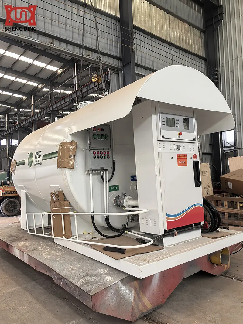
1. Explosion-Proof Refueling Machine:
- Components: This is the user-facing equipment, consisting of an explosion-proof motor, explosion-proof pump, explosion-proof flowmeter (meter), explosion-proof solenoid valve, explosion-proof control box, explosion-proof keypad, explosion-proof display, explosion-proof refueling nozzle with breakaway valve, and explosion-proof oil transfer hose.
- Function: Its core function is to safely and accurately meter and dispense fuel. All electrical components (motor, control circuit, display, etc.) are enclosed in a housing that meets explosion-proof standards (e.g., flameproof, increased safety, or intrinsically safe). This ensures that even if an internal spark or fault occurs, it will not ignite the potentially explosive oil-gas mixture outside. Explosion-proof fuel nozzles typically have a self-sealing function to prevent oil spills; breakaway valves automatically disconnect and seal the fuel line if the vehicle is accidentally driven away, preventing leaks.
2. Double-walled, leak-proof fuel storage tanks:
- Composition: Typically constructed of a double-walled steel structure (composite materials are also available), with a gap (called an interlayer) between the two tank walls. These tanks are equipped with highly sensitive leak detection systems (such as vacuum pressure monitoring and liquid sensors).
- Purpose: These are the core containers for fuel storage. The double-walled structure provides dual protection. Even if a leak occurs in the inner tank, the leaked fuel is confined within the interlayer, and the detection system promptly triggers an alarm to prevent it from seeping into the soil and groundwater. This significantly reduces the risk of leaks causing fires, explosions, and environmental pollution at the source. The tank itself is also fireproof and explosion-resistant.
3. Explosion-proof oil pipelines and emergency shut-off systems:
- Composition: The pipeline connecting the fuel storage tank and the fuel dispenser is made of anti-static, corrosion-resistant materials (such as seamless steel pipe). Explosion-proof emergency shut-off valves (usually pneumatic or hydraulic, intrinsically safe) are installed at key locations (typically at tank farm outlets and fuel dispenser entrances). This system is linked to combustible gas detectors, high-level alarms on liquid level gauges, fire detectors, and emergency buttons on the control panel.
- Purpose: Upon detecting an abnormal condition (such as a pipeline rupture, a fuel dispenser being struck, excessive combustible gas concentrations, a fire, or manually pressing the emergency stop button), the emergency shut-off valve automatically closes within a split second (usually <= 3 seconds), shutting off the oil source and preventing further leaks. This serves as a critical safety barrier to prevent accidents from escalating.
4. Oil and Vapor Recovery System:
- Components: This system is divided into oil and vapor recovery during unloading (primary recovery) and oil and vapor recovery during refueling (secondary recovery). It primarily includes a sealed unloading port, oil and vapor recovery piping, an oil and vapor recovery nozzle and coaxial hose, and an oil and vapor treatment device (such as an adsorption or condensation type).
- Purpose: During the unloading and refueling process, volatilized oil and vapor are effectively collected and treated or recovered into the tank, significantly reducing the concentration of combustible oil and vapor vapors in the operating area, lowering the risk of explosion while also complying with environmental requirements.
5. High Liquid Level Monitoring Alarm:
- Components: An explosion-proof liquid level sensor installed inside the oil storage tank and an external control and alarm device.
- Purpose: Real-time monitoring of the tank liquid level. When the liquid level reaches a set upper limit (e.g., 90%-95% of volume), an audible and visual alarm is issued. The system can also interlock and close the inlet valve or notify the operator to prevent spills during unloading (oil spills are a major fire and explosion hazard).
6. Combustible Gas Concentration Alarm:
- Components: Explosion-proof gas detectors (typically measuring the LEL percentage of combustible gases such as methane and propane) are installed in key locations where oil and gas may accumulate, such as the oil storage area and under fuel dispensers.
- Purpose: Continuously monitor the concentration of combustible gases in the environment. When the concentration reaches a preset low alarm value (e.g., 20% LEL), an early warning is issued, prompting inspection. When the concentration reaches a high alarm value (e.g., 50% LEL), a strong alarm is issued and the system can interlock and activate the emergency shut-off system or ventilation equipment, providing timely warning of a potentially explosive environment.
7. Anti-static and Grounding System:
- Components: All metal equipment (tanks, pipelines, dispensers, cranes, etc.) are securely connected via wires and ultimately to a qualified grounding electrode (grounding grid). An electrostatic grounding alarm is installed at the oil unloading area.
- Purpose: Ensures that static electricity generated during equipment operation and loading and unloading is quickly conducted to the ground, eliminating the risk of static discharge sparks igniting oil and gas. The electrostatic grounding alarm ensures that the unloading vehicle and the tank system are connected at the same potential before unloading is permitted.
8. Automatic Fire Extinguishing Device:
- Components: Small, temperature- or smoke-activated automatic fire extinguishing devices (such as S-type aerosols or ultra-fine dry powder) are typically installed in key locations within the oil storage area (especially near submersible pumps) and within dispensers.
- Purpose: Automatically detect and rapidly release fire extinguishing agent in the early stages of a fire, extinguishing the initial fire and preventing its spread.
9. Overall Structural Fire and Explosion-Proof Design:
- Components: The entire equipment is mounted on a sturdy skid-mounted base. The tank farm and the dispenser operation area are typically separated by a firewall. Protective fencing is installed on the exterior of the equipment.
- Purpose: Provides physical isolation and protection, limiting the impact of an accident. Fireproof walls can slow the spread of flames.
II. The Role of Explosion-Proof Refueling Equipment (Comprehensive Safety Benefits)
The core function of skid-mounted fuel station explosion-proof refueling equipment is to comprehensively and multi-layeredly prevent and control fire and explosion accidents, ensuring the safety of personnel, equipment, and the environment. This is specifically demonstrated by:
- 1. Intrinsic Safety: Through explosion-proof electrical equipment (dispensers, instruments, detectors), double-walled leak-proof tanks, and fire- and explosion-proof structures, the risk of ignition and fuel leaks is eliminated or significantly reduced at the source.
- 2. Leak Prevention and Monitoring: Double-walled tanks, leak detection, high-level alarms, and emergency shut-off valves ensure maximum prevention of leaks, enabling early detection and rapid shut-off of leaks.
- 3. Explosive Environment Control: The oil and vapor recovery system effectively reduces oil and vapor concentrations in the operating area, making it difficult to reach the Lower Explosive Limit (LEL); combustible gas alarms provide continuous monitoring and early warning.
- 4. Ignition Source Control: Explosion-proof electrical equipment prevents internal sparks from leaking; a comprehensive electrostatic grounding system eliminates static sparks; and the equipment structure prevents collision and friction sparks.
- 5. Rapid Accident Suppression: The emergency shut-off system instantly shuts off the oil supply at the first sign of an accident; and the automatic fire extinguishing device extinguishes incipient fires.
- 6. Personnel and Equipment Protection: Physical isolation designs such as guardrails and firewalls protect operators and external equipment from direct impact in the event of an accident.
- 7. Environmental Protection: Oil leaks are prevented from contaminating soil and groundwater, and oil and vapor volatilization from polluting the atmosphere is reduced.
- 8. Improved Management Safety: The integrated automatic monitoring and alarm system makes safety management more convenient and responsive.


III. Maintenance and Care of Explosion-Proof Fueling Equipment (Comprehensive Safety Benefits)
1. Daily Inspection and Basic Maintenance (Performed by Operators, Usually Daily or Each Shift)
1.1. Visual Inspection:
- Overall Appearance: Inspect the tank, pipelines, fuel dispensers, guardrails, etc. for obvious damage, deformation, rust, oil leaks, or oil odor.
- Grounding Connections: Visually inspect all grounding wires for secure connections, no breaks, and no severe rust. Ensure that the oil unloading static grounding clamps and alarms are in proper condition.
- Signage: Check that safety warning signs, operating instructions, and no-fire signs are legible and intact.
- Firefighting Equipment: Check that fire extinguishers are under normal pressure, have seals intact, are unobstructed, have sufficient firefighting sand, and have all the necessary tools.
- Site Environment: Ensure the station area is clean, free of flammable debris, and that drainage ditches are unobstructed.
1.2. Functional Inspection:
- Combustible Gas Alarm: Confirm that the power indicator is functioning normally and there are no alarm signals (the sensor can be tested periodically using standard gas according to regulations, but daily inspection should focus on the status).
- High Liquid Level Alarm: Check that the display is normal and there are no abnormal alarms.
- Emergency Shutoff Button: Check that it is intact and unobstructed (do not press unless in an emergency).
- Fuel Pump and Breakaway Valve: Check that the fuel pump switch is flexible and the self-sealing function is effective (a brief test may be performed), that the breakaway valve is not deformed or leaking, and that the hose is not cracked, bulged, or worn.
- Vapor Recovery System: Check that the fuel pump air cap is intact and that the coaxial hose is not damaged.
1.3. Cleaning and Maintenance:
- Clean the fuel dispenser housing, display, and keypad, and keep the equipment clean (use a damp cloth; avoid using flammable solvents).
- Clean the fuel pump nozzle and self-sealing air inlet to prevent blockage.
- Clean any oil or accumulated water around the equipment.
2. Regular Maintenance (Performed by professional repair personnel or manufacturer's service personnel, according to a scheduled cycle)
2.1. Explosion-Proof Dispenser Maintenance:
- Frequency: Monthly/Quarterly/As per manufacturer's requirements.
- Content:
- Clean and remove dust from the interior (power off, ensure explosion-proof surface protection).
- Check that all explosion-proof mating surfaces are intact, clean, and undamaged, and that all fastening bolts are tightened (critical! This directly impacts explosion-proof performance).
- Check that the explosion-proof motor and pump operate normally, with sound and temperature.
- Check the flowmeter, encoder, and sensor connections and status.
- Test the solenoid valve for proper switching.
- Calibrate metering accuracy (according to metering calibration cycle requirements).
- Inspect internal wiring for signs of aging, looseness, or overheating.
- Replace worn nozzle components (such as O-rings, valve core, etc.).
2.2. Fuel Tank and Accessories Maintenance:
- Frequency: Quarterly/Semi-annually/Annually.
- Contents:
- Leak Detection System Testing: Perform manual or automatic testing regularly as specified in the equipment manual to confirm that the system can effectively detect and alarm interlayer leaks (extremely important!).
- Level Gauge Calibration and Testing: Check whether the level gauge display is consistent with the manually gauged value, and test whether the high-level alarm function is effective.
- Barrier and explosion-proof materials (if applicable): Check their effectiveness (usually performed by a professional testing agency according to the specified age limit).
- Manholes, oil gauges, and breather valves: Check whether the gaskets are aged, whether they open and close freely, and whether the breather valves are unobstructed and free of blockage.
- External Inspection of the Tank and Pipelines: Focus on inspecting welds, flange connections, and valves for leaks and corrosion. Perform wall thickness testing if necessary.
2.3. Emergency Shutoff System Testing:
- Frequency: At least monthly (mandatory by law).
- Contents:
- Simulate trigger conditions (such as pressing the emergency button, shorting the high-limit signal of the combustible gas alarm, simulating an excessively high liquid level alarm) to verify that the emergency shutoff valve can reliably close within 3 seconds. Check the valve for leaks after closing (no leakage).
- Manually reset the valve after testing to confirm that the system has returned to normal operation.
- Check the pressure and leaks in the pneumatic/hydraulic lines.
2.4. Combustible Gas Alarm System Maintenance:
- Monthly: Check the status monthly. Calibrate at least once every six months (using standard gas).
- Contents:
- Clean the sensor probe dust cover.
- Test the audible and visual alarm functions.
- Calibrate using a standard concentration of combustible gas (such as 50% LEL isobutane or methane) to ensure accurate alarm values (lower alarm of 20-25% LEL, upper alarm of 50% LEL).
- Check the sensor lifespan and replace it if expired.
2.5. Vapor Recovery System Maintenance:
- Monthly: Quarterly/six months.
- Contents:
- Check the fuel nozzle cap for leaks and the coaxial hose for damage or leaks.
- Check the vacuum pump (if applicable) for operation.
- Check the condition of the pipeline valves. Check the condition of treatment devices (such as activated carbon canisters) and replace adsorbent materials as needed.
- Gas-to-Liquid Ratio Testing: Regularly (e.g., annually), have a professional organization test the gas-to-liquid ratio of the refueling vapor recovery system to ensure it meets the standard (usually 1.0-1.2). If not, adjustments and repairs are required.
2.6. Electrical System Maintenance:
- Interval: Every six months/year.
- Content:
- Comprehensive Inspection of Explosion-Proof Performance: Check the cleanliness, integrity, and tightening torque of the explosion-proof surfaces of all explosion-proof electrical equipment (junction boxes, control boxes, lighting, detectors, etc.) (most important).
- CCheck the integrity of cable entry seals (glands).
- CCheck line insulation for signs of aging and damage.
- CTest emergency lighting (if any).
- CMeasure Ground Resistance: At least once a year, ensure the ground resistance value is <=10¦¸ (or meets design requirements).
2.7. Pipes, Valves, and Flanges:
- Interval: Every quarter/six months. Contents: Check all pipe supports for security, flange joints for leaks, valves for flexible opening and closing, no internal or external leakage, and valve stem lubrication.
2.8. Automatic Fire Extinguishing Device:
- Cycle: According to the product manual (usually annual pressure/weight check, replacement every several years).
- Content: Check that the pressure gauge/indicator is in the green zone, the nozzles are not clogged, and the activation device (temperature/smoke sensor) appears normal. Replace the reagents when due.
3. Key Principles and Precautions for Maintenance
- 3.1. Qualification Requirements: Maintenance, inspection, and testing of special equipment such as explosion-proof electrical equipment, pressure vessels (if any), and measuring instruments must be performed by qualified organizations and personnel.
- 3.2. Power-off Operation: Before opening explosion-proof electrical equipment or performing repairs that may generate sparks, the power must be disconnected and a warning sign must be displayed. Use explosion-proof tools.
- 3.3. Explosion-proof Surface Protection: When disassembling explosion-proof equipment, be sure to carefully protect the explosion-proof mating surfaces to avoid scratches and bumps. During assembly, ensure that mating surfaces are clean and free of foreign matter, and tighten bolts to the specified torque.
- 3.4. Operation with Defects Strictly Prohibited: Any abnormality (such as alarms, leaks, abnormal noises, or malfunctions) must be immediately discontinued, the cause identified, and repaired. Operation may only resume after passing testing.
- 3.5. Spare Parts: Use original spare parts or those that meet explosion-proof rating and specification requirements. Substitution is strictly prohibited.
- 3.6. Complete Records: Detailed records of the content, time, personnel, results, and replaced parts of each inspection, maintenance, test, repair, and calibration are maintained, creating an equipment maintenance file. This is crucial for traceability and demonstrating compliance.
- 3.7. Adequate Training: Operators and maintenance personnel must undergo rigorous training and be familiar with the equipment's structure, principles, operating procedures, safety risks, and emergency response measures. They must be certified and certified.
- 3.8. Compliance with Regulations: Operations must strictly adhere to relevant national and local safety standards (such as AQ 3002) and the maintenance manual provided by the equipment manufacturer. 3.9. Emergency Plan Drills: Regular emergency drills for emergencies such as leaks, fires, and explosions should be conducted to ensure personnel are familiar with procedures and equipment usage.
Maintenance of skid-mounted fuel station explosion-proof refueling equipment is a systematic, professional, and mandatory task. It goes beyond simple cleaning and part replacement; rather, it involves rigorous periodic inspections, testing, calibration, and preventive maintenance to continuously verify and safeguard the integrity and reliability of the entire safety system. Only by integrating and strictly implementing daily inspections, regular maintenance, professional testing, standardized record-keeping, and personnel training can we minimize potential hazards, ensure that this highly integrated safety protection system remains effective at all times, and truly achieve the "intrinsically safe" design goal of skid-mounted fuel stations. Neglecting maintenance can render even the most advanced explosion-proof equipment ineffective, posing significant risks.
In Summary
The above explanation should provide a new understanding of skid-mounted fuel station explosion-proof refueling equipment. It is an essential feature of skid-mounted fuel stations and plays an indispensable role in protecting the normal operation of the station. Moreover, the danger alarm system it is equipped with can effectively nip the danger in the bud. Therefore, when we purchase skid-mounted fuel stations in the future, we must carefully check the performance of the explosion-proof refueling device, and we must also perform maintenance and upkeep on time when operating the gas station. If you have any related questions, please feel free to call us for consultation.
Written by
TAIAN SHENGDING METAL CONTAINER MANUFACTURING CO., LTD.
Editor Wang
www.self-bunded-tank.com
WhatsApp:+86 152 5486 3111
Email:shengdingtank@126.com
- WhatsApp
- E-MailE-Mail:shengdingtank@126.com
- WeChatWeChat:15254863111


